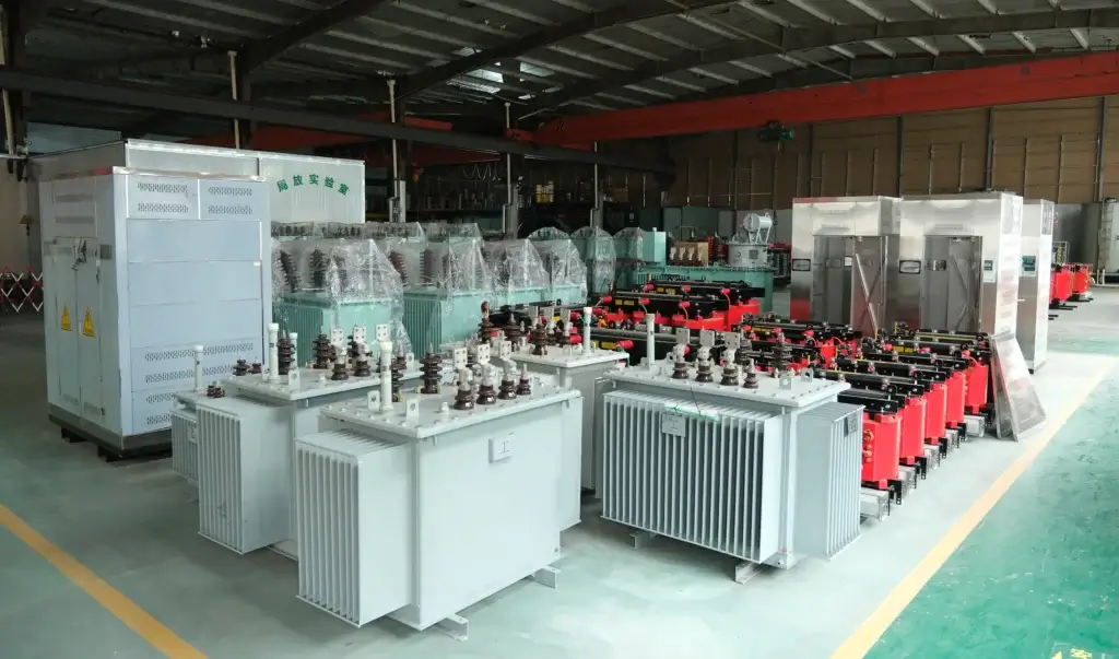
An undersized distribution transformer rarely fails on the day it is commissioned. It runs. It gets hot. It ages faster than the design intended.
The fault stays invisible because the unit meets its nameplate. The nameplate was simply the wrong target.
This guide works backwards. It does not explain how to size a transformer. It explains what happens when the size is wrong, what it looks like on site, and which record proves it.
How an Undersized Distribution Transformer Fails in Year Three
The first three signals are usually small.
An oil thermometer reads high on a day the load is unremarkable. A Buchholz relay gives a light gas alarm. Winding resistance measured during the annual service drifts away from the values recorded at commissioning.
None of these stops production. That is precisely why they get ignored.
The mechanism behind them is thermal, not electrical. A sustained hot spot drives the cellulose in the insulation paper through depolymerisation. The paper does not burn. It loses mechanical strength and becomes brittle.
A brittle winding still carries current. It simply cannot survive the next short circuit or the next inrush. That is why the failure looks sudden even though it took three years to build.
The evidence exists, but only if someone kept it: the operating temperature log, dissolved gas analysis results, and the historical winding resistance readings.
One more pattern is worth naming. When such a unit finally fails, the failure is usually blamed on the fault that finished it — a downstream short circuit, a lightning surge, a switching event. The unit was not destroyed by that event. It was already unable to survive it.
Temperature Rise: The First Victim
Three temperatures matter, and they are not the same number.
Top-oil temperature is the easiest to measure and the least useful on its own. Average winding temperature sits above it. The hot spot sits above both, and it is the one that ages the paper.
IEC 60076-2 sets the limits and the measurement method. The actual limit depends on the insulation thermal class and the cooling mode, so it is read from the standard rather than quoted from memory.
The critical behaviour is this: under overload, the hot spot rises faster than the average. The average can still look acceptable while the hot spot has already passed its limit.
In an undersized distribution transformer, that gradient is the whole problem. The oil stays calm, the average stays plausible, and the paper in the middle of the winding pays for it.
The same mechanism applies across our oil-immersed transformer range, from small distribution units upward.


Why Top-Oil Alone Misleads
A gauge on the tank wall reads oil, not winding.
Oil moves heat slowly, and it mixes. The winding stays hotter than the oil around it, and the middle of the winding stays hotter than its ends. A top-oil reading can look calm while an internal hot spot is already running away.
This is why overloaded units look normal on the panel until they do not.
What the Test Report Gives You
The temperature rise type test under IEC 60076-2 measures top-oil and average winding rise at defined conditions. It does not measure the hot spot directly.
The hot spot is derived, using the gradient assumptions of the standard. That derivation is sound for a new unit at rated load. It becomes optimistic once the load profile sits above the rating for long periods.
Read the report for what it is: a baseline, taken on one day, at one condition.
The Ageing Curve
Thermal ageing is steep, not linear. The commonly cited rule of thumb is 6 to 8 K per halving of thermal life. Treat it as an industry approximation, not a guaranteed number.
The practical conclusion is short. A unit run at 110% for years does not lose ten percent of its life. It loses far more.
Losses Compound Instead of Scaling
Two loss components behave differently.
No-load loss is set by the core and stays roughly constant. Load loss follows the square of the current, because it is resistive loss plus stray loss. At 120% load, load loss is about 1.44 times the rated figure.
That ratio is arithmetic, not opinion. One point two squared is one point four four.
A worked illustration makes it concrete. Set load loss at 10 units and no-load loss at 2 units at rated load. Total loss is 12.
Run the same unit at 120% and load loss becomes 14.4 units. Total loss is now 16.4, an increase of 37% in losses for a 20% increase in load.
The delivered power rose by a fifth. The heat to remove rose by more than a third. Those two numbers do not move together, and that is the whole argument.
There is a second effect. Higher temperature raises conductor resistance, which raises loss again. The penalty feeds itself.
Efficiency peaks where load loss equals no-load loss. For distribution transformers that point usually sits in the middle of the load range, not at the top. Running above it means paying more per delivered kilowatt hour, every hour.
Short-Circuit Withstand Under Stress
A short circuit tests two things at once, and overload weakens both.
Electromagnetic force scales with the square of the current. The same square law that raises loss raises the mechanical stress on the winding.
At the same time, copper softens as it heats. Yield strength falls with temperature, so the conductor resists deformation less well exactly when the force is highest.
IEC 60076-5 is the basis for short-circuit withstand. A type test proves the design at the tested condition. It does not describe a unit that has run hot for three years.
That gap is the real risk. The report in your file describes a new transformer. The transformer on your plinth is not new. This is why an undersized distribution transformer can pass every routine test and still sit close to collapse.
Damage also accumulates without any single event being remarkable. A through-fault that clears in a few cycles leaves a small permanent deformation. Ten of them leave a winding that has lost its preload and its shape.
Insulation degradation and mechanical fatigue are separate mechanisms. Overload drives both at the same time.
Two documents narrow the uncertainty. The short-circuit test report shows what the design was proven to withstand. The impedance value measured on your own unit shows whether that design was actually built.
When Over-Sizing Is Also Wrong
The opposite error costs money too, and it is easier to spot on a quotation.
No-load loss runs 24 hours a day, whether the plant is working or not. A unit two sizes too large pays that loss permanently for no output.
Light load brings other penalties. Magnetising current and reactive demand are proportionally larger. Inrush current is higher. Footprint, oil volume and initial price all rise.
There is a regulatory angle most buyers miss. Efficiency rules are written in capacity bands. Stepping up one rating can move the unit into a stricter band with tighter loss limits. The larger unit may then need a more expensive core to comply.
For indoor projects using resin-insulated dry-type transformers, the load harmonic content matters as well, because it changes the usable rating.
The same worked units show the cost. With load loss at 10 and no-load loss at 2, a unit running at half load carries load loss of 2.5. No-load loss stays at 2. Nearly half of all losses are then paid while producing half the output.
Oversizing by two steps makes that ratio worse, not better. You carry a larger core’s magnetising loss on a load it was never meant to serve.
Capacity is a band, not a direction. Bigger is not safer. Correct is safer.
Sizing Checks That Settle the Question
Five inputs decide whether an undersized distribution transformer is what you are actually buying.
- Load profile. Daily and seasonal, not a single peak figure. A plant that peaks for two hours a day is a different problem from one that runs at 85% all week.
- Demand factor and diversity. What actually runs together, not what is installed. Nameplate totals overstate real demand in almost every plant.
- Temperature rise and ambient correction. Site ambient and altitude change the usable rating. A unit chosen for a temperate site may be derated where it is actually installed.
- Impedance and voltage regulation. Affects motor starting and downstream voltage. A larger unit with higher impedance is not automatically the better answer for starting loads.
- Market efficiency class. EU 2019/1783, US 10 CFR Part 431 or the local equivalent. This decides the loss level you are allowed to buy, not just the one you prefer.
Two more are often skipped: harmonic content, which matters for dry-type units through the K-factor, and the expansion horizon, which decides whether to buy the larger unit now or parallel a second one later.
For loading beyond nameplate, the reference to consult is IEC 60076-7, the loading guide. It sets out how ambient, cooling and load shape interact. It is not a licence to run at 130% indefinitely.
FAQ
Can an undersized distribution transformer run above its rated capacity continuously?
Only within limits set by ambient temperature, cooling mode and the loading guide. Continuous overload accelerates ageing even when nothing trips. The unit does not warn you; it simply arrives at the end of its life earlier.
Does a larger transformer always last longer?
No. A larger unit runs cooler at the same load, which helps. But it also carries higher no-load loss for its whole life and may sit at low efficiency. Correct sizing beats both directions.
How do I know my unit is running hot?
Three signs: top-oil temperature higher than similar units on the same site, gas relay alarms without an external fault, and winding resistance drifting between annual tests. Any one of them justifies a dissolved gas analysis.
If load grows by 20%, can I keep the same transformer?
Sometimes, but only after checking ambient, cooling and the loading guide. A unit already running near its limit at today’s load has no margin for tomorrow’s, and the loss penalty grows faster than the load does.
Is adding a second unit better than replacing the first?
It can be, if the two can run in parallel. Parallel operation requires matching vector group, close impedance, and a tap arrangement that keeps circulating current under control. Where those conditions are met, a second unit adds capacity without discarding the first one.
Where they cannot be met, a mismatched pair will circulate current between itself and run hotter than either unit alone. Replacing is then the cheaper answer, even at the higher headline price.