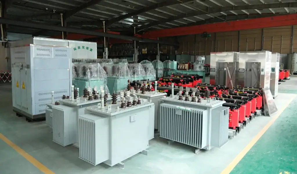
A distribution transformer is expected to run continuously for 25 to 30 years. Whether it actually reaches that service life is decided long before the unit is energised — inside the factory, at five specific stages of production.
Most overseas buyers never see those stages. They receive a quotation, a data sheet, and a finished cabinet at the port. The gap between ordered and built is where failures start. Typical causes: undersized conductors, under-dried insulation, voids in cast resin, and test sheets that were never generated.
The transformer manufacturing process step by step runs through five controlled stages:
- Core fabrication — CRGO silicon steel cut and stacked in step-lap configuration to control no-load loss (P0).
- Coil winding — copper conductors wound with designed insulation build to withstand short-circuit forces and impulse voltage.
- Drying and impregnation — moisture removed and insulation consolidated, by vapour-phase drying for oil-immersed units or vacuum casting for dry-type units.
- Final assembly — leads, tap changer and bushings installed, tank sealed and pressure-tested.
- Routine testing — every unit measured against its guaranteed losses, ratio and dielectric strength before dispatch.
At each stage, one parameter decides whether the unit is sound or merely looks sound. Those parameters are listed below, together with the standard each one is verified against.
Why the Manufacturing Process Is the Only Reliable Audit Evidence
A trading agent can forward a factory certificate, a catalogue, and a test report. What an agent cannot do is let you watch the core being stacked, the winding being dried, or the loss test being run on your own unit.
This is why buyers who have been burned once stop asking “what certificates do you have” and start asking “can I witness the routine test”. The manufacturing record — cut sheets, drying curves, casting logs, test data — cannot be manufactured retroactively for a specific order.
The five stages below are written so that each one produces a document you can demand and check.


Step 1: Core Fabrication — Cutting, Stacking and No-Load Loss
The core determines no-load loss (P0), which is present 24 hours a day regardless of load. It is the single largest contributor to lifetime energy cost in a lightly loaded distribution transformer.
Material
Copper-clad aluminium (CCA) cuts cost and short-circuit withstand together. Lower conductivity means higher loss for the same cross-section. The thermal expansion mismatch also ages the insulation faster.
Cutting
Laminations are cut on CNC slitting and cross-cutting lines.
Burr height is typically held below 0.02 mm. Dimensional tolerance is typically within ±0.1 mm. Both are internal process limits, not standard requirements.
Excess burr short-circuits adjacent laminations. That raises eddy-current loss and local heating.
Step-lap stacking
Laminations are stacked in 45-degree full-miter joints. The joints are multi-step, not butt joints. Each step overlaps the joint of the layer beneath.
This closes the air gap in the magnetic path.
The result is lower magnetising current and lower no-load loss. Industry figures cite 30% to 70% lower magnetising current. That range depends on core design.
The definitive number is on the routine test report.
Clamping and earthing
Limbs and yokes are clamped with non-magnetic steel frames. Insulated through-bolts hold the assembly.
The core is earthed at exactly one point. A second earth path creates a circulating current. That current overheats the frame.
Document to demand: core cutting list, CRGO mill certificate, and the measured P0 on the final test report.
Step 2: Coil Winding — Conductor, Insulation Build and Short-Circuit Strength
The winding must survive two different stresses. One is continuous thermal load. The other is the mechanical force of a short circuit.
Conductor material
Annealed electrolytic copper is the baseline. Conductivity must be at least 100% IACS. That equals a resistivity of 0.017241 ohm·mm²/m at 20 °C, as defined in IEC 60028.
Copper-clad aluminium (CCA) and plain aluminium cut cost and short-circuit withstand together. Lower conductivity means higher loss for the same cross-section. The mismatch in thermal expansion also accelerates insulation ageing under cyclic load. In tenders where short-circuit withstand matters, specify the conductor material explicitly — an omission is an invitation.
Winding construction
- Low-voltage windings use copper foil or continuously transposed conductor. This spreads current evenly and resists radial short-circuit forces.
- High-voltage windings use multilayer cylindrical or continuous disc construction. Insulation is reinforced at the line end. Impulse stress is highest there.
Insulation build
Layer insulation using diamond-pattern epoxy-coated paper (DMD), thermally upgraded kraft, or Nomex where high-temperature class is required. After drying, the coated paper bonds into a rigid block that resists movement under short-circuit forces.
Document to demand: winding process card, conductor mill certificate, and measured resistance of all three phases.
Acceptance criterion: phase resistance unbalance must not exceed 2%. Line-to-line unbalance must not exceed 1%. Both are measured at the same temperature.
This is the conventional limit under IEC 60076-1 / GB 1094.1. An out-of-balance result points to a wrong turn count or a poor joint.
Step 3: Drying and Impregnation — Removing Moisture Before It Becomes Failure
Water is the primary enemy of transformer insulation. One percent moisture in cellulose insulation can cut dielectric strength by an order of magnitude. It also accelerates paper ageing dramatically.This stage cannot be inspected visually after the fact, which is why it is the most commonly skipped step in low-cost production.
Oil-immersed units: vapour-phase drying
The assembled core-and-coil goes into a vapour-phase plant or a high-vacuum oven.
The process target is residual moisture below 0.5% by weight. That target is typical practice, not a standard value. Verification is the drying curve, not a visual check.
Oil filling then follows under vacuum. Distribution-class units are typically filled at 133 Pa or lower. Higher voltage classes use lower absolute pressure.
Vacuum filling prevents air pockets. Trapped air would later start partial discharge.
Dry-type units: vacuum casting
Resin and hardener are mixed and degassed under vacuum. The typical range is 1 to 5 mbar. The mix is then cast into the mould under vacuum.
Curing follows a stepped profile, for example 80 °C, 110 °C, then 140 °C. This lets the resin gel without shrinkage cracks.
Acceptance here is measurable, not cosmetic.
Partial discharge must not exceed 10 pC at 1.3 times rated voltage. That limit is set by IEC 60076-11.
A casting with trapped voids fails this test. A perfect surface proves nothing.
Document to demand: drying curve or casting log with vacuum and temperature records, plus the PD result for dry-type units.
Step 4: Final Assembly — Leads, Tap Changer and Pressure Tightness
Lead connection
Current-carrying joints are made by hydraulic crimping or silver-copper brazing, then insulated with crepe paper or heat-shrink build. A high-resistance joint is a hot spot. It will not appear in any test at rated current. It appears years later as dissolved gas.
Tap changer and bushings
The off-circuit tap changer is set to the specified range. ±2 x 2.5% is typical.
Bushings are selected for system voltage and for site pollution level. Creepage distance follows the specified IEC 60815 class.
Tank and sealing
The tank is welded, shot-blasted to Sa 2.5, and coated with a multi-layer paint system. After assembly, sealed tanks are pressure-tested — typically 20 to 50 kPa held for 24 hours depending on tank design — and checked for leakage at every welded seam and gasket face.
For corrugated-wall tanks, the wall itself provides the expansion volume; there is no conservator and no oil-to-air contact, so the oil does not oxidise and the desiccant breather maintenance item disappears entirely.
Document to demand: pressure test record with pressure value and hold time, paint system specification and dry film thickness, and the tap changer position record.
Step 5: Routine Testing — Where Every Claim Is Either Confirmed or Exposed
Routine tests are performed on every unit, not on a sample. They are defined in IEC 60076-1 (liquid-immersed) and IEC 60076-11 (dry-type), with test procedures detailed in the corresponding parts of the series.

Two further points separate a real test report from a decorative one:
- Sound level is measured per IEC 60076-10, which defines the method — not the limit. Limits are contractual, and any figure quoted must state whether it is sound pressure level at 1 m or sound power level; the two differ by more than 10 dB.
- Loss values must be traceable to the target market. The legal efficiency floor is not universal: the EU applies Regulation (EU) 2019/1783 with EN 50588-1, the United States applies 10 CFR Part 431 Subpart K, and Gulf markets apply SASO/ESMA registration. The same 1000 kVA unit may need two different loss designs for two different destinations.
Process and Quality Control Matrix

What a Buyer Should Request at Each Stage
- Before production — approved drawings, loss guarantees, and the material specification for CRGO grade and conductor.
- During production — photographs of core stacking and winding, and the drying or casting log with dates.
- Before packing — the routine test report for your specific serial number, with measured values, not just “pass”.
- At dispatch — pressure test record, paint DFT record, and packing list matching the serial number on the nameplate.
A supplier who can produce all four without delay is a manufacturer. A supplier who produces only a certificate is not.
Related Equipment
- For outdoor distribution with sealed corrugated tanks and no oil-to-air contact, see Hermetically Sealed Oil-Immersed Transformers (S11 / S13 / S20).
- For indoor installations where fire codes prohibit combustible liquid, see Resin-Insulated Dry-Type Transformers (SCB11 – SCB18).
Frequently Asked Questions (FAQ)
How long does transformer manufacturing take?
Standard distribution units in the 50 to 2500 kVA range, at 10 kV to 35 kV, typically require 25 to 35 days from drawing approval to seaworthy packing, including routine testing. Non-standard voltages, special tap ranges, or third-party witness testing add time to that schedule.
How can I confirm which CRGO grade was actually used?
The mill certificate alone proves nothing — it can belong to any coil in the warehouse. The reliable proof is the measured no-load loss on the routine test report for your serial number, compared against the guaranteed P0 in the contract. If the measured value is materially worse than the guarantee, the core is not what was ordered.
Can I witness the routine tests myself?
Yes, and it is the single most effective quality measure available to a buyer. Factory acceptance testing can be witnessed in person or by a nominated third party such as SGS, TÜV, or Bureau Veritas. Arrange it in the purchase order, not after production starts, so the test date is scheduled rather than improvised.
Why does a dry-type unit need a partial discharge test but an oil-immersed unit usually does not?
In cast resin, any trapped void becomes a site of continuous internal discharge that erodes the insulation from the inside, with no visible external sign. The 10 pC limit in IEC 60076-11 is a direct check on casting quality. In oil-immersed units the liquid impregnates the insulation and fills voids, so partial discharge is not a routine test for distribution class equipment — but dissolved gas analysis in service serves a similar early-warning purpose.