Writing an accurate technical specification for a distribution transformer is one of the most critical responsibilities for electrical project managers, EPC contractors, and plant engineers. A poorly specified transformer creates decades of operational headaches: sizing it too small causes frequent thermal trips during motor start-ups, while sizing it too large results in continuous no-load electrical waste.
Furthermore, failing to define precise loss limits and vector configurations leads to failed acceptance audits, harmonic overheating, and grid compliance disputes.
To properly specify a distribution transformer, you must verify three fundamental engineering parameters:
- Capacity Sizing (kVA): Calculate real peak demands to keep continuous loading within the optimal 70% to 85% economic efficiency window, including a 20% future expansion allowance.
- Guaranteed Losses (𝑃0 and 𝑃𝑘): Demand exact numerical watt limits in accordance with IEC 60076 standards rather than accepting ambiguous “low-loss” commercial claims.
- Vector Group Selection: Specify Dyn11 for modern four-wire distribution grids to eliminate zero-sequence harmonic circulation and accommodate up to 100% neutral unbalance currents.
Follow this technical checklist to engineer an airtight procurement specification for your upcoming installation.

Transformer Capacity Sizing: Balancing Peak Demand and Efficiency
Selecting the correct transformer rating requires calculating true apparent power (kVA) rather than simply totaling connected equipment nameplates.
The Fundamental Sizing Formula
To determine the required transformer capacity, apply standard industrial diversity and power factors:
Transformer Sizing Formula:
S (kVA) = (P_total × Kd) / (cosφ × η)
- P_total = Total connected active load in kilowatts (kW)
- Kd = Demand factor (typically 0.75 – 0.85 in manufacturing facilities where not all machines run simultaneously)
- cosφ = System operating power factor (typically 0.85 with capacitor compensation)
- η = Comprehensive electrical drive efficiency (typically 0.90 – 0.95)
Avoid the “Oversizing Trap”
Never double the calculated capacity simply for safety. Transformers achieve their highest operational efficiency when loaded between 70% and 85% of rated capacity. Operating a transformer continuously below 30% load wastes substantial utility power through constant core excitation losses (P0).
Account for Motor Starting Inrush
If your facility drives heavy industrial pumps, compressors, or crushers, verify direct-on-line (DOL) motor starting currents. Starting currents reach 6 to 8 times full-load current (FLC). Your specification should mandate that terminal voltage drop during the largest motor start remains strictly within 10% to 15%.
Loss Evaluation: Differentiating No-Load (P0) and Load Losses (Pk)
Evaluating transformer efficiency requires looking at total cost of ownership (TCO). While purchase price (CapEx) is paid once, energy losses (OpEx) consume cash 24/7 for 25 to 30 years.
Total Transformer Losses = No-Load Loss (P0, Core Iron Loss) + Load Loss (Pk, Winding Copper Loss)
No-Load Loss (P0 – Core Losses)
- What It Is: The continuous electrical power absorbed by the magnetic core laminations whenever the transformer is energized, regardless of whether secondary loads are connected.
- Specification Target: Require high-permeability, cold-rolled grain-oriented (CRGO) silicon steel laminations assembled with 45-degree full-miter step-lap joints. Step-lap stacking minimizes magnetic flux leakage and reduces core noise below 50–55 dB.
Load Loss (Pk – Winding Losses)
- What It Is: The thermal energy dissipated across the primary and secondary coils due to electrical resistance. This loss increases with the square of the operating load.
- Specification Target: Mandate 100% oxygen-free electrolytic copper windings with electrical conductivity >= 100% IACS. Strictly reject copper-clad aluminum (CCA) substitutes in critical industrial tenders to maintain mechanical short-circuit strength.
Recommended Product Technology:
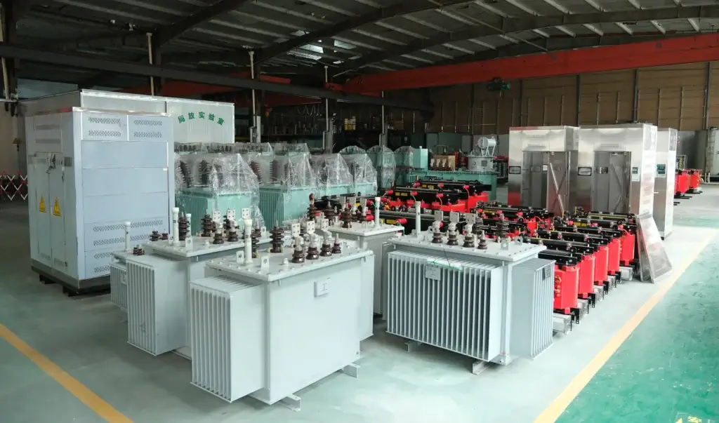
- For outdoor substations, heavy industrial plants, and utility feeders, specify high-efficiency Hermetically Sealed Oil-Immersed Transformers (S11, S13, S20), which cut no-load losses by up to 30% via elastic corrugated cooling tanks.
- For indoor cleanrooms, commercial buildings, and underground substations where fire codes prohibit combustible liquids, specify Cast Resin Dry-Type Transformers (SCB11-SCB18) utilizing Class F/H flame-retardant epoxy vacuum encapsulation.
Vector Group Selection: Why Dyn11 Beats Yyn0 in Modern Grids
Selecting the vector configuration determines phase displacement and neutral current behavior across three-phase distribution networks.
High-Voltage Delta (D) Connection vs. Low-Voltage Star (yn) Connection:
- Primary Delta (D): Traps 3rd-order harmonics (150 Hz) inside its closed-loop winding, preventing harmonic distortion from polluting upstream transmission lines.
- Secondary Star with Neutral (yn): Supplies stable 400V phase-to-phase and 230V phase-to-neutral power for both commercial equipment and plant machinery.
- Superior Harmonic Suppression
Non-linear commercial and industrial loads (such as variable frequency drives, computers, and LED power supplies) inject heavy 3rd-order harmonic currents.
- In a Dyn11 configuration, the delta-connected high-voltage winding traps triplen harmonics inside its closed loop, preventing harmonic distortion from polluting upstream transmission grids.
- In a Yyn0 configuration, 3rd harmonics cannot circulate, leading to distorted secondary voltage waveforms and overheating neutral lines.
- Handling Neutral Unbalance
Dyn11 allows 100% rated current on the neutral conductor. This permits unbalanced single-phase lighting and office loads across phases without causing neutral point displacement.
Yyn0 limits neutral current to below 25% of phase current, making it unsuitable for modern mixed-use facilities.
The Engineering Specification Checklist for Procurement
When publishing a Request for Quotation (RFQ) or engineering tender, verify that all parameters below are defined:

Factory Acceptance Testing (FAT) and Compliance Verification
Never approve a transformer delivery based solely on an internal vendor declaration. Require compliance with international standards backed by third-party accreditation:
- Routine Test Reports (Every Unit): Mandate factory routine tests covering winding resistance, voltage ratio, phase displacement, no-load loss, load loss, and separate-source AC withstand tests.
- Type Test Certification: Insist on comprehensive type test reports from national-level testing bodies stamped with CNAS and ilac-MRA accreditation marks. Key verifications include temperature rise limits, lightning impulse withstand, and dynamic short-circuit endurance.
- CE Compliance: Verify conformity with European Low Voltage (LVD) Directive 2014/35/EU and harmonized standard IEC 60076.
Frequently Asked Questions (FAQ)
What is the difference between ONAN and ONAF cooling ratings?
ONAN (Oil Natural Air Natural) indicates standard passive cooling through corrugated radiator fins. ONAF (Oil Natural Air Forced) adds auxiliary cooling fans to increase heat dissipation, boosting transformer throughput capacity by 20% to 30% during peak demand intervals.
When should I specify 1.5× surge withstand insulation?
If your installation connects to long overhead transmission lines exposed to severe tropical lightning storms or unstable rural grids, specify 1.5× surge withstand margins. This provides reinforced turn-to-turn insulation and expanded creepage distances against switching surges.
Can a Dyn11 transformer be paralleled with a Yyn0 transformer?
No. Transformers with different vector group clock numbers possess an internal phase angle displacement (Dyn11 has a 30-degree phase shift, whereas Yyn0 has zero shift). Paralleling them creates severe circulating short-circuit currents between secondary windings, causing immediate breaker tripping.